

 简体中文
 English
 Español
Don't hesitate to send a message
Search
Recent Post
Newsletter
Key Components of an Industrial Pressure Control System
Pressure shows up in nearly every industrial process. It pushes liquids through pipes, feeds air into production equipment, and powers hydraulic operations. When pressure shifts without warning, even a small fault can ripple through the whole line. Equipment slows, product quality drifts, or workers have to stop the process to hunt for the cause.
An industrial pressure control system keeps those shifts within an acceptable range for the job. It does more than adjust pressure. It also monitors conditions, reacts to changing demand, and protects equipment when pressure goes past a safe limit.
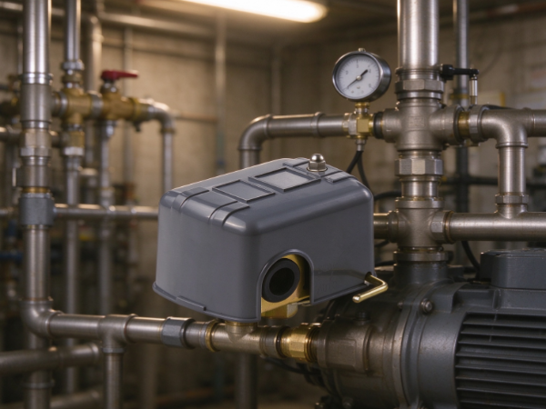
A typical system combines pressure sensors, controllers, control valves, regulators, and safety devices. Each part has its own role, and they all have to work together. Knowing how they interact helps engineers, maintenance teams, and buyers make better decisions about design and operation.
What Does an Industrial Pressure Control System Do?
The system manages the pressure of a gas or liquid inside a process. It may hold supply pressure steady, respond to changes in demand, or stop pressure from reaching a dangerous level.
The exact setup depends on the application. A compressed air system has different needs from a hydraulic circuit or a liquid transfer line. The basic purpose is the same, though: measure pressure, compare it with the required condition, and adjust when needed.
Take a production line that runs several machines on compressed air. When more machines start up, air demand climbs. If the supply can't keep pace, pressure drops. A control system detects the change and adjusts the equipment that maintains the supply.
A pressure control system commonly performs these functions:
- Pressure monitoring: Checks the current pressure in the process.
- Pressure adjustment: Changes flow or supply conditions to keep pressure in range.
- Equipment protection: Helps prevent damage from excessive or unstable pressure.
- Process coordination: Lets pumps, compressors, valves, and other equipment respond to changing needs.
- Fault detection: Alerts operators when the system departs from expected conditions.
What it can do depends on the installed equipment. Some applications use a simple mechanical arrangement. Others rely on electronic monitoring and automatic control. The components may differ, but each must suit the pressure medium, the environment, and the process.
How Do Pressure Sensors and Transmitters Monitor the System?
A control system needs reliable information before it can make a useful adjustment. Pressure sensors and transmitters supply it by detecting pressure at chosen points in the process.
A sensor responds to the pressure acting on its sensing element. Depending on the design, it converts that pressure into an electrical signal or another form the control system can read. A transmitter typically sends a matching signal on to a controller, monitor, or other receiving device.
People often use the two terms interchangeably, but their roles differ a little. The sensor is the element that detects pressure. The transmitter usually adds the components needed to pass a usable measurement to other devices.
Where you measure matters. A sensor near a pump outlet can read a different pressure from one farther down the pipeline. Restrictions, elevation changes, flow conditions, and equipment operation all affect the reading. Place the measuring point where it reflects the condition the system needs to watch.
Consider the process medium when choosing a sensor. A device that works with clean air may not suit a liquid carrying particles or chemicals that can harm its sensing surface. Temperature, vibration, moisture, and the surrounding environment can also change how it performs.
Common problems include blocked pressure connections, damaged wiring, sensor drift, and incorrect installation. A faulty reading can lead the controller to make an unneeded adjustment, or to miss a real pressure change.
Check pressure measurements during commissioning and routine maintenance. If a reading doesn't match what the process is doing, inspect the sensor, its connections, and the conditions at the measurement point before you change other settings.
What Role Does the Pressure Controller Play?
The controller is the decision-maker in an automatic pressure control system. It takes information from the measuring device and decides whether an adjustment is needed.
A basic control process involves three things: the desired pressure, the measured pressure, and the gap between them. The controller uses that gap to decide how the system should respond.
Say a process needs steady pressure while equipment starts and stops through a work cycle. If measured pressure falls below the target, the controller may tell a pump, compressor, or control valve to increase supply. If pressure rises, it may cut output or restrict flow.
The response depends on the control strategy and the available equipment. A simple controller may just switch equipment on or off. A more advanced one may adjust output gradually to soften sudden changes.
Controllers can be mechanical, electronic, or part of a larger automation system. Mechanical devices often rely on physical forces to react to pressure changes. Electronic controllers process measurement signals and send commands to connected equipment. In automated plants, pressure control may also be coordinated with other process variables.
The controller has to be configured for the behavior of the system it manages. If it reacts too aggressively, pressure may swing up and down around the target. If it reacts too slowly, the process can stay out of range longer than it should.
It also depends on accurate measurements and a working actuator. A correctly configured controller can't hold pressure steady if its sensor sends bad data or its control valve fails to respond.
So when you investigate unstable pressure, look at the complete control loop. Don't assume the controller is the culprit.
How Do Pressure Control Valves and Regulators Adjust Pressure?
Control valves and pressure regulators turn a control decision into a physical change. Depending on their design and position, they can restrict, release, or adjust the flow of a gas or liquid.
A pressure control valve typically changes its opening in response to a control signal or a mechanical mechanism. That adjustment affects flow and helps hold the required pressure. The valve may sit in a supply line, a return line, or anywhere that changing flow can influence the pressure being controlled.
A regulator usually does a more specific job. It reduces or maintains pressure at a downstream point, even when upstream supply or downstream demand changes, within the regulator's operating capability.
For example, a compressed air supply may run at a pressure that isn't right for every connected tool. A regulator can step the incoming pressure down to suit the equipment it feeds. That separates each application's needs from the conditions of the main supply.
The two devices are related, but you can't swap them in every situation. A control valve is often one piece of a larger control loop, while a regulator may work automatically through its own internal mechanism. Some systems use both to meet different pressure requirements.
The choice depends on the system's function, the medium, the expected changes in demand, and the response you need. Valve materials and seals must also be compatible with the process fluid and the surroundings.
Installation can matter as much as selection. Wrong flow direction, poor placement, contamination, or bad connections can cause unstable control or leaks. Regular inspection catches wear and other changes before they disrupt production.
Why Are Pressure Relief Valves and Safety Devices Necessary?
Pressure control isn't only about keeping a process steady. It also has to cover situations where normal control can't stop pressure from climbing too high.
A pressure relief valve gives excess pressure a protective way out once the system reaches its set relief condition. Depending on the application, the released medium may go to a suitable collection or discharge location. The arrangement must follow the relevant safety requirements for the process.
A relief valve serves a different purpose from an ordinary control valve. A control valve adjusts the process during normal operation. A relief valve protects equipment when pressure exceeds the permitted limit. Don't use it as a routine substitute for proper pressure regulation.
Other protective components include pressure switches, high-pressure alarms, shutdown devices, and interlocks. A pressure switch can trigger an electrical action at a set pressure. An alarm warns an operator of an abnormal state. A shutdown function may stop equipment or interrupt a process when continued operation could create a hazard.
Together these devices give several layers of protection. Their effectiveness still depends on correct selection, installation, inspection, and testing. A relief path can become blocked, a switch can fail to operate, and an alarm can go unnoticed if monitoring is poorly managed.
Safety equipment must also suit the medium and the consequences of a release. Gas, steam, and liquid systems may need different arrangements. Consider where discharge points sit, who might be exposed, and what a release could do to nearby equipment.
A pressure control system should therefore keep normal operating control and emergency protection clearly separate. Both are necessary, but they deal with different conditions.
Which Supporting Components Help the System Operate Reliably?
Sensors, controllers, valves, and relief devices get most of the attention. Several supporting components also shape performance. Overlook them and the system can become hard to run or maintain.
| Component | Main function | Why it matters |
|---|---|---|
| Pressure gauges | Display local pressure readings | Allow operators to check conditions directly |
| Pressure switches | Trigger an action at a specified pressure condition | Support alarms, equipment control, and protective functions |
| Signal cables and connectors | Carry measurement and control signals | Help maintain communication between devices |
| Actuators | Move valves or other adjustable equipment | Convert control commands into physical movement |
| Filters and strainers | Remove certain contaminants from the process medium | Help reduce blockage and wear in downstream components |
| Pipes, fittings, and seals | Connect the equipment and contain the medium | Support pressure integrity and limit leakage |
| Control panels | Organize monitoring, controls, and operator interfaces | Make system operation and fault response easier to manage |
Gauges stay useful even when electronic monitoring is installed. A local reading lets a technician compare the displayed pressure with the value the control system reports. If the two differ, the technician has a place to start looking for a sensor or signal fault.
Actuators deserve attention too. A controller may send the right command, but a valve won't respond properly if its actuator is damaged, stuck, or too weak. The pressure problem can look like a control issue when the real cause is mechanical.
Filters and strainers manage contamination where particles can damage or block equipment. They must suit the process and be maintained as the system requires. A clogged filter can itself restrict flow and cause pressure changes.
Connections and seals count as well. Small leaks waste energy, create safety concerns, and make pressure hard to hold. In liquid systems, leakage can also contaminate nearby equipment or work areas.
Treat these supporting parts as members of the complete system, not as unrelated accessories.
How Do the Main Components Work Together?
The components form one connected process. Each device contributes to the result, and a problem in one part can affect the whole arrangement.
A typical automatic pressure control sequence goes like this:
- A pressure sensor measures the condition at a selected point.
- A transmitter sends the measurement to the controller.
- The controller compares the reading with the required operating condition.
- A control signal goes to a valve, pump, compressor, or other adjustable device.
- The equipment changes its operation, which affects pressure in the process.
- The sensor measures the new condition, so the controller can adjust again if needed.
This cycle repeats while the system runs. The aim is to follow changing demand without causing needless pressure swings.
Picture a water line serving several production stations. When one station draws more water, pressure in the shared line may fall. A sensor picks up the change and reports it to the controller. The controller adjusts the pump or a related valve to meet the demand. When demand shifts again, the system adjusts again.
A separate relief device stands ready to deal with excess pressure if a fault or unusual condition occurs. It doesn't replace the normal control sequence.
How well this works depends on compatibility between components. The sensor must measure the relevant condition, the controller must read the signal correctly, and the actuator must respond as intended. If one part is a poor match for the others, the system may react too slowly or make unnecessary adjustments.
Integration also covers electrical connections, communication signals, mounting, and maintenance access. Clear documentation helps technicians see how the parts are connected and which device to check when a fault appears.
What Should Buyers and Maintenance Teams Consider?
Choosing pressure control equipment means more than comparing individual parts. Buyers need to understand how the equipment will be used and how each piece fits the overall system.
The pressure medium is a good starting point. Air, water, oil, steam, and chemical fluids put different demands on materials, seals, sensing elements, and valve construction. Confirm compatibility for your actual operating conditions instead of assuming it from the product category.
The operating environment matters too. Heat, vibration, moisture, dust, and corrosive substances can shorten component life and hurt measurement reliability. Equipment in a clean indoor room may need a different design from equipment outdoors or beside a production process.
Other points to consider:
- Pressure requirements: Identify the normal operating condition and the limits that call for a protective response.
- Flow demand: Consider how pressure may change as connected equipment starts, stops, or runs at different loads.
- Control method: Decide whether mechanical regulation, automatic electronic control, or a combination fits.
- Safety requirements: Confirm that protective devices and discharge arrangements match the application and applicable rules.
- Maintenance access: Check whether sensors, valves, filters, and other serviceable parts can be inspected without needless disruption.
- System compatibility: Make sure new equipment works with existing pipes, fittings, electrical connections, and control interfaces.
- Documentation and support: Review installation instructions, maintenance guidance, spare-part availability, and the supplier's ability to answer technical questions.
Maintenance teams should also set up a practical inspection routine. It may include checking for leaks, comparing pressure readings, inspecting connections, confirming valve movement, and testing alarms or shutdown functions according to the applicable procedures.
When pressure becomes unstable, work through the system methodically. Compare local gauge readings with sensor signals, check for changes in flow demand, inspect filters and valves, and confirm that actuators respond to control commands. This lowers the risk of replacing a working component while the real fault sits elsewhere.
An industrial pressure control system is a group of connected devices, not a single piece of equipment. When you understand what each component does, it's easier to judge system requirements, investigate operating problems, and plan maintenance around the needs of the process.
OUR PRODUCTS
Recommended Products
-
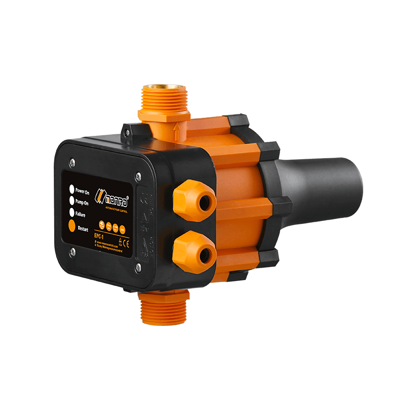 EPC-1
Monro EPC-1 model pump controller is the classic and basic type, was loved by user in the global mar...
-
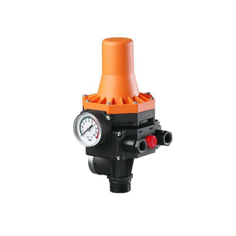 EPC-3
Monro EPC-3 spain design auto on and off press control, an intelligent and economical system designe...
-
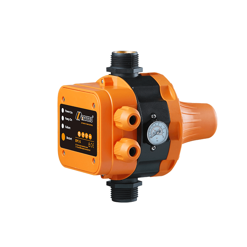 EPC-5
Monro EPC-5 model automatic pump control, a device which assembled on the water pump (recommended si...
-
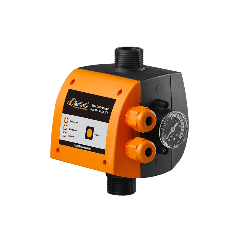 EPC-9
Monro EPC-9 model pressure controller, is a big power device for automatic control and protection of...
-
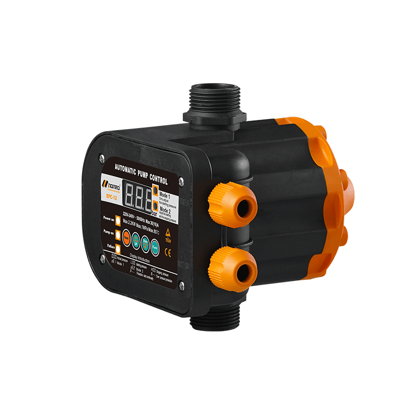 EPC-12
Monro EPC-12 smart top-level automatic pump control is a multi-function model combined with traditio...
-
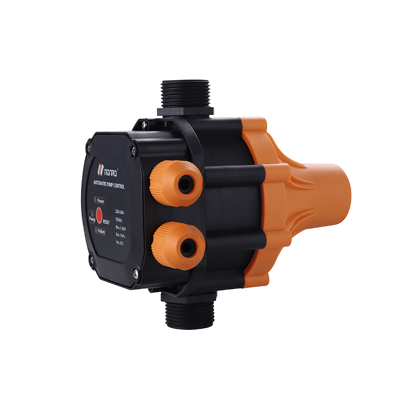 EPC-14
Monro EPC-14 model pressure control is a big power device for automatic control and protection of el...
-
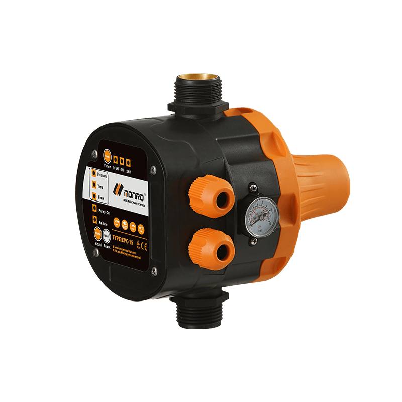 EPC-15
Monro EPC-15 model automatic pump control, a device which assembled on the water pump (recommended s...
-
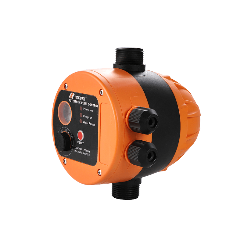 EPC-16
 is the new patent pump controller by Monro. Its key highlight is tooless (manual knob) start...
contact us
find our office
find our office
Committed to providing professional pressure control solutions for various types of water pumps and air compressors.
Mobile
 Wechat
Copyright © 2024 Zhejiang Monro M&E Co., Ltd. All Rights Reserved.
Wholesale Pressure Control Switch Manufacturer
