

 简体中文
 English
 Español
Don't hesitate to send a message
Search
Recent Post
Newsletter
What Components Make Up a Pump Control System
Pumps move liquids through industrial plants, commercial buildings, water treatment facilities, farms, and many other places. They supply water, transfer chemicals, circulate coolant, and support production processes. A pump seldom runs well on its own, though. It needs a control system to manage operation, react to changing conditions, and protect the equipment attached to it.
A pump control system combines electrical devices, sensors, control units, and protective components. Each does a specific job. Some start and stop the pump. Others watch operating conditions or step in when something goes wrong. Together they keep fluid movement under control.
The exact setup depends on the pump type, the application, the environment, and the control requirements. A simple installation may need only a basic panel and a few protective devices. A large industrial system may add automatic controls, many sensors, communication equipment, and several pumps working as a group.
Knowing the main components helps operators, engineers, and maintenance teams understand how the system works, and makes it easier to pick suitable equipment for a given pumping job.
What Is a Pump Control System ?
A system is a set of electrical and mechanical components that manages pump operation. It decides when the pump starts, how it runs, and when it stops. In many applications it also adjusts operation as pressure, flow, liquid level, or other process conditions change.
Without proper controls, a pump may keep running with no liquid to move. It may work under excessive pressure, or fail to respond when fluid demand shifts. Any of these can harm the pump, pipes, valves, and other equipment.
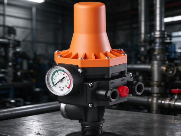
The control system prevents this by gathering information and reacting to it. A water supply system, for instance, may use pressure sensors to notice a pressure drop. The controller then starts the pump to restore supply.
A storage tank might use level sensors instead. Once the liquid hits a certain level, the system signals the pump to start or stop.
Control can be manual, automatic, or a mix. Manual control gives operators direct command of the pump. Automatic control lets the equipment respond to preset conditions without constant human attention.
Many systems add monitoring and communication functions. Operators can check equipment status, spot abnormal conditions, and manage pumping from a control room or another remote location.
Which Components Form the Main Control Structure?
Designs vary, but several basic components turn up in most installations. Together they form the electrical and control backbone that lets the pump run.
The main components are:
- Control panel: Houses the electrical devices and serves as the central point for operating and monitoring.
- Controller: Processes incoming signals and decides how the pump should respond.
- Motor starter: Controls the electrical connection that starts and stops the pump motor.
- Protective devices: Detect electrical or operating faults and help prevent damage.
- Sensors: Collect data on pressure, flow, temperature, and liquid level.
- Switches and relays: Pass control signals along and manage electrical operations.
- Display and communication devices: Let operators see system conditions and interact with the equipment.
Wiring and signal circuits connect them all. How they're arranged depends on the control method and the number of pumps.
A small installation may pack several functions into one compact enclosure. A complex industrial system may spread them over multiple panels and field devices.
The key point: no single component runs everything. The system works because its parts communicate.
What Role Does the Pump Control Panel Play?
The control panel is the central electrical enclosure. It gathers many of the devices that operate, protect, and monitor the pump.
Inside you may find circuit breakers, contactors, motor starters, relays, controllers, terminal blocks, and other electrical parts, laid out according to the system design.
The panel is also the operator's interface to the pump. Depending on the build, it may carry start and stop buttons, selector switches, indicator lights, and a display screen.
Every control has a clear purpose. The start button commands the pump to run. The stop button interrupts normal operation. A selector switch may let the operator choose manual or automatic mode.
Indicator lights give quick visual feedback. They can show whether the pump is running, stopped, powered, or faulted.
The physical design counts as well. The panel needs enough room for components, wiring, and heat dissipation, and its enclosure should suit the surroundings.
A panel in a clean indoor facility has different protection needs from one outdoors or beside water treatment equipment. Dust, moisture, temperature swings, and vibration all affect the choice of enclosure.
A tidy panel makes maintenance easier too. Clear labels and accessible wiring help technicians trace connections and inspect equipment without fuss.
How Does the Controller Manage Pump Operation?
The controller is the decision-maker in an automatic system. It receives signals from sensors, switches, and other devices, processes them, and sends commands to the pump or related equipment.
Controller types vary by application. A basic system may use electrical relays and pressure switches. More advanced setups use programmable logic controllers or dedicated pump controllers.
A programmable controller follows a set of operating instructions that define how the pump reacts to different conditions.
Take a water supply installation. When pressure falls, the pressure sensor signals the controller. It checks the conditions and sends a start command to the motor control equipment.
Once pressure returns to the required level, the controller can stop the pump or adjust its operation. Supply stays stable and nobody has to start and stop the pump by hand.
Controllers can also manage several pumps. They may rotate the operating order, which spreads running time and keeps one pump from carrying the whole load.
Some systems include a standby pump. If the duty pump fails, the controller can raise an alarm and switch to the standby unit, provided the system is designed for automatic changeover.
What a controller does depends on its programming and available inputs. It may handle start and stop commands, operating sequences, alarms, and communication with outside monitoring equipment.
Its performance is only as good as the information it receives. Wrong sensor signals or poor electrical connections can trigger unexpected responses, so correct installation and signal checks are part of regular maintenance.
Why Are Motor Starters and Protective Devices Necessary?
A pump motor needs a controlled electrical supply. Motor starters and protective devices manage that supply and lower the risk of electrical damage.
A motor starter connects and disconnects the motor from power. It usually works together with a contactor and other electrical parts.
The contactor is an electrically operated switch. When it gets a control signal, it closes the circuit and power flows to the motor. When the signal stops, it cuts the motor off.
Several starting methods exist, chosen by motor, pump application, electrical supply, and operating needs.
Direct starting connects the motor to the supply through switching equipment. Other arrangements control how power reaches the motor during startup. Some systems use variable frequency drives to adjust motor speed and allow controlled acceleration.
Protective devices have a different but equally important job. They detect abnormal electrical conditions and cut the supply when needed.
Common protective components include:
| Component | Main Function |
|---|---|
| Circuit breaker | Interrupts the electrical supply when certain fault conditions occur |
| Overload relay | Protects the motor against sustained excessive electrical load |
| Fuse | Disconnects a circuit when excessive current causes it to operate |
| Phase protection relay | Detects problems with the electrical phase supply |
| Earth leakage protection | Helps detect leakage current and reduce electrical hazards |
These devices don't all react to the same faults, so they complement one another.
An overload relay, for example, protects a motor that draws too much current over time. A circuit breaker trips when a more serious electrical fault appears.
Protection must also fit the actual equipment. Wrong selection or wiring can leave parts of the system exposed, so regular inspection should confirm the devices still work properly.
How Do Sensors and Switches Monitor Pump Conditions?
Sensors and switches supply the information that automatic control depends on. They watch conditions in the pumping system and send signals to the controller.
Without them, the controller would know little about what's happening in the pipes, tanks, and connected equipment.
Each type of sensor watches a different condition.
Pressure sensors and pressure switches
Pressure sensors measure pressure in a pipeline or pumping system and convert changes into signals the controller can process.
Pressure switches do something similar but usually act when pressure reaches a preset switching point. They can start or stop pumps in water supply and pressure maintenance applications.
Flow sensors and flow switches
Flow sensors track liquid movement through a pipe. They show whether fluid is moving and whether the flow meets operating requirements.
Flow switches react when flow reaches a defined condition. They can detect a lack of circulation or confirm fluid is passing through a given section.
Liquid level sensors
Level sensors monitor how much liquid sits in a tank, reservoir, or storage vessel. Their signals control filling and draining.
A tank filling system, for example, can start the pump when the level drops and stop it when the tank is full.
Temperature sensors
Temperature sensors watch heat in the motor, the liquid, or nearby equipment. They can warn when temperatures leave the permitted range.
That helps where fluid temperature or motor heating can affect operation.
Placement matters. A pressure sensor on an unsuitable section of pipe may not reflect the true state of the system. A level sensor has to be compatible with both the liquid and the tank structure.
Regular cleaning, inspection, and signal testing keep monitoring reliable.
What Is the Function of Relays, Timers, and Variable Frequency Drives?
Relays, timers, and variable frequency drives shape how a pump responds to commands. Not every installation has them, but systems needing extra control functions often do.
Relays
A relay uses an electrical signal to operate a switching contact, so a low-power control circuit can manage another electrical circuit.
In pump systems, relays may pass signals between sensors, controllers, alarms, and motor control equipment.
They can also provide electrical interlocking, which stops certain operations from happening at the same time when the design requires it.
Timers
Timers trigger actions based on preset times. They can delay a pump start, hold a pump running for a set period, or sequence several pumps.
A drainage system, for instance, may need a pump to keep running briefly after a control signal changes. A timer can handle that.
Timers also support alternating pump operation and scheduled processes, depending on whether the application needs time-based control.
Variable frequency drives
A variable frequency drive controls the electrical supply to a motor so its speed can change. The system can then respond to shifting demand.
In a water distribution system, demand rises and falls through the day. A pump running at one constant speed may not match it.
A drive can adjust motor speed using signals from pressure or flow sensors. When demand climbs, the pump speeds up. When it falls, the pump slows.
That reduces needless operation and helps manage pressure changes in the pipeline.
Drives can also provide controlled starting and stopping, which softens sudden changes and limits mechanical stress on connected equipment.
They aren't needed everywhere. A simple system with steady operating conditions may do fine with conventional motor control.
How Do Alarms, Displays, and Communication Devices Improve Monitoring?
A pump control system must do more than run the motor. Operators need to know its condition and catch problems when they arise.
Displays, alarms, and communication devices provide that visibility.
An operator interface may use indicator lights, meters, or a touchscreen. Users can view operating status and interact with the control system.
Depending on configuration, the display may show:
- Pump running or stopped status.
- Current pressure and flow conditions.
- Liquid level information.
- Motor operating conditions.
- Active alarms and fault messages.
- Manual or automatic operating mode.
Alarms warn of abnormal conditions such as low liquid level, excessive pressure, motor overload, high temperature, or communication failure.
Some alarms use indicator lights. Others sound audibly or show messages on a screen. Larger installations may send notifications to a remote monitoring platform.
Communication equipment lets the control system exchange information with other industrial devices, so operators can watch several pumps from one place.
A water treatment facility, for example, may have pumps scattered across different areas. A connected monitoring system gathers the data and displays it in a central control room.
Remote monitoring doesn't replace local inspection. Operators still need to check physical equipment, electrical connections, and mechanical condition. Still, having operating data at hand helps them recognize problems and schedule maintenance.
How Do Different Components Work Together in a Pump Control System?
Each component has its own job, yet the system works through their cooperation. Sensors gather information, controllers process signals, switching devices manage power, and protective equipment reacts to abnormal conditions.
A water supply system shows how this plays out.
When demand rises, pipeline pressure may fall. A pressure sensor notices and signals the controller. The controller checks conditions and commands the motor starter.
The contactor connects the motor to the supply and the pump starts. If a variable frequency drive is fitted, it can adjust motor speed to the pressure required.
While running, sensors keep watching. Once pressure reaches the required level, the controller can slow or stop the pump, depending on the control arrangement.
If something abnormal happens, protective devices may cut the supply. The controller can also set off an alarm to alert the operator.
The table below summarizes the flow:
| Component | Information or Action | Contribution to System Operation |
|---|---|---|
| Pressure sensor | Detects pipeline pressure | Provides operating information |
| Controller | Processes sensor signals | Determines the required response |
| Motor starter | Connects or disconnects motor power | Starts and stops the pump |
| Variable frequency drive | Adjusts motor speed | Responds to changing demand |
| Protective relay | Detects abnormal conditions | Helps prevent equipment damage |
| Alarm device | Signals a fault or warning | Alerts operators |
| Display interface | Shows operating information | Supports monitoring and control |
The same general process applies elsewhere, though sensors and control logic differ.
A drainage pump may lean heavily on liquid level data. A chemical transfer system may need flow monitoring and extra safety interlocks. A cooling water system may use temperature and pressure signals to keep circulation going.
The number and type of components should match real operating needs, not just add complexity.
What Should Be Considered When Selecting Pump Control Components?
Choosing components means understanding the pump, the liquid, the installation environment, and the expected operating conditions.
What works in one application may not suit another, so selection should consider how the whole system will operate.
Pump and motor compatibility
Control equipment must match the motor and pump. Starters, contactors, protective devices, and variable frequency drives should be chosen to fit the electrical and operating requirements.
Control method
The application may call for manual control, automatic control, or both. A simple water transfer system may need only start and stop. A multi-pump installation may need automatic sequencing and standby control.
Operating conditions
Pressure, flow, temperature, and liquid level all affect component choice. So does the liquid itself. Corrosive or contaminated fluids may need sensors and fittings made of suitable materials.
Installation environment
Panels and field devices may face dust, moisture, vibration, or temperature changes. Enclosure and protection ratings should suit the location.
Maintenance access
Technicians should be able to inspect, test, and replace components easily. Clear wiring labels and reachable controls simplify the work.
System expansion
Some installations will later need more pumps, sensors, or remote monitoring. The control structure should allow reasonable expansion without reworking the entire system.
OUR PRODUCTS
Recommended Products
-
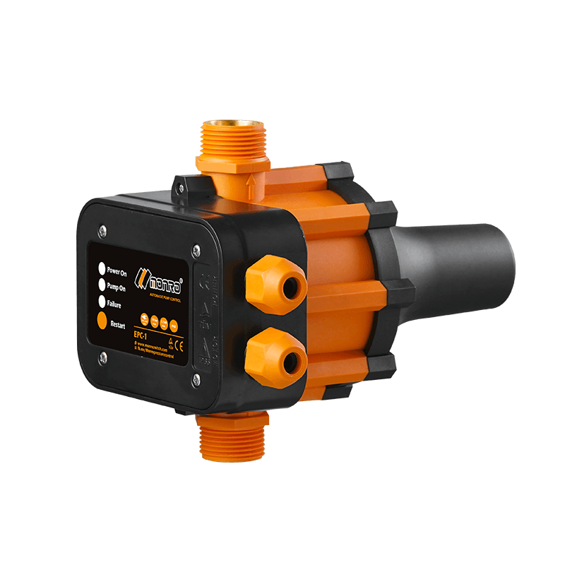 EPC-1
Monro EPC-1 model pump controller is the classic and basic type, was loved by user in the global mar...
-
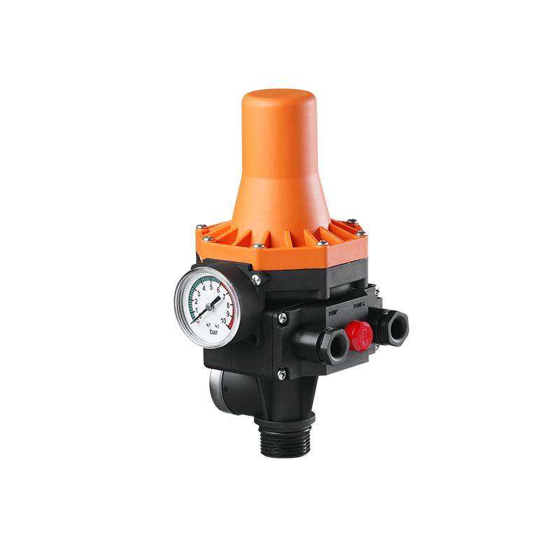 EPC-3
Monro EPC-3 spain design auto on and off press control, an intelligent and economical system designe...
-
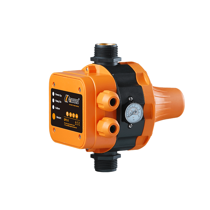 EPC-5
Monro EPC-5 model automatic pump control, a device which assembled on the water pump (recommended si...
-
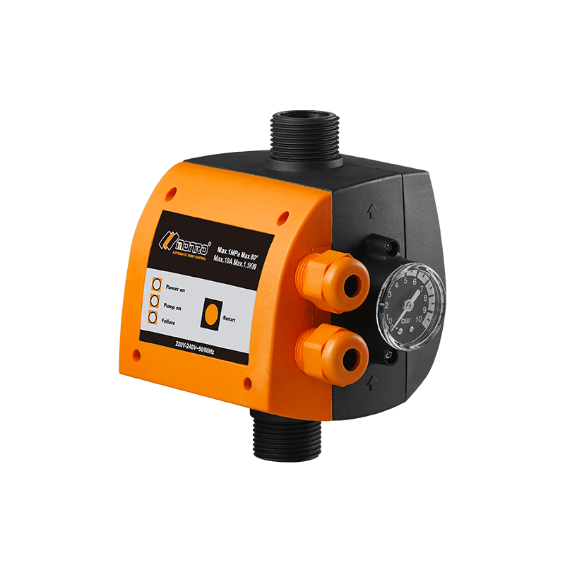 EPC-9
Monro EPC-9 model pressure controller, is a big power device for automatic control and protection of...
-
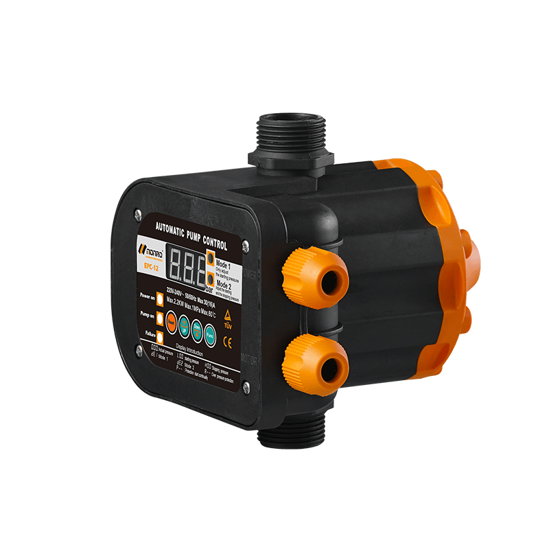 EPC-12
Monro EPC-12 smart top-level automatic pump control is a multi-function model combined with traditio...
-
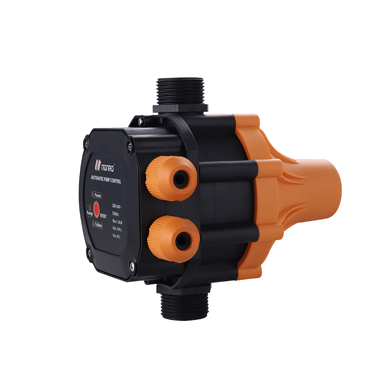 EPC-14
Monro EPC-14 model pressure control is a big power device for automatic control and protection of el...
-
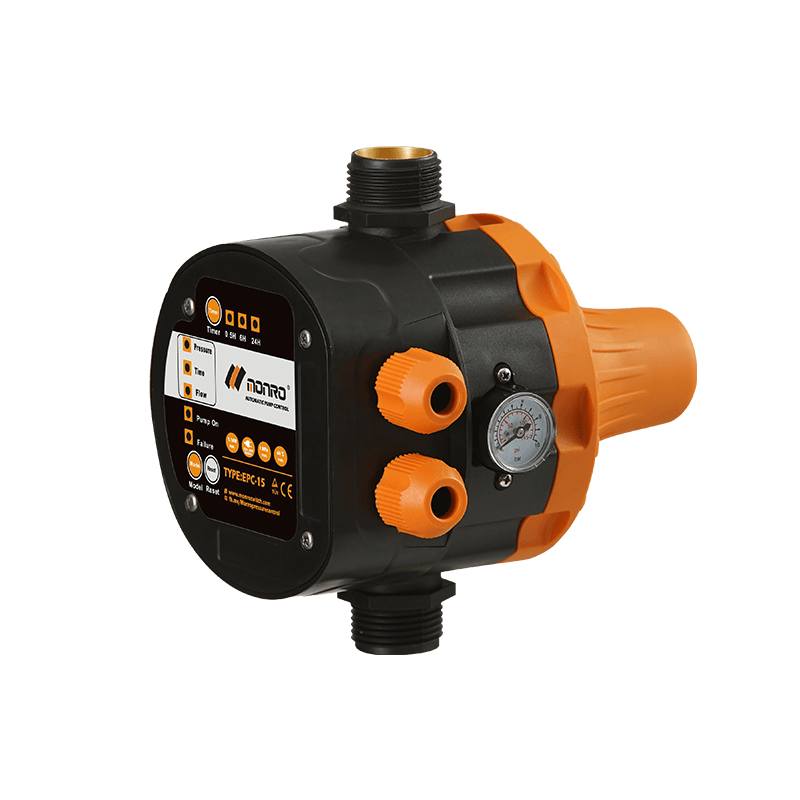 EPC-15
Monro EPC-15 model automatic pump control, a device which assembled on the water pump (recommended s...
-
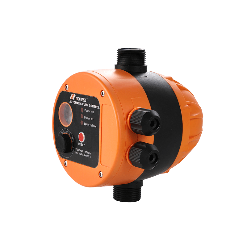 EPC-16
 is the new patent pump controller by Monro. Its key highlight is tooless (manual knob) start...
contact us
find our office
find our office
Committed to providing professional pressure control solutions for various types of water pumps and air compressors.
Mobile
 Wechat
Copyright © 2024 Zhejiang Monro M&E Co., Ltd. All Rights Reserved.
Wholesale Pressure Control Switch Manufacturer
